Deciphering Radio Schematics: A Step-by-Step Guide
Understanding radio schematics is key to successful repair. This article teaches you how to read and interpret schematics, identifying components and tracing circuits.
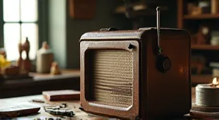
For anyone delving into the rewarding world of antique radio restoration, mastering the ability to read and interpret radio schematics is absolutely crucial. These diagrams, often appearing cryptic to the uninitiated, are the roadmaps to understanding the complex circuitry within these vintage marvels. This guide breaks down the process step-by-step, equipping you with the foundational knowledge to confidently tackle radio repair projects.
Understanding the Basics: Symbols and Conventions
Radio schematics utilize a standardized language of symbols to represent electronic components. Familiarizing yourself with these symbols is the first hurdle.
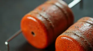
- Resistors: Typically represented as a zig-zag line or a rectangular box. The value is indicated numerically (e.g., 100 ohms).
- Capacitors: Often symbolized by two parallel lines. Different capacitor types (e.g., electrolytic, ceramic) may have slightly different symbols.
- Inductors (Coils): Depicted as a coiled line.
- Vacuum Tubes: Each type of tube (e.g., rectifier, amplifier, detector) has a specific symbol. Pay close attention to the tube number (e.g., 6SN7, 12AX7) – this will be critical for sourcing replacement tubes.
- Diodes: A triangle pointing to a vertical line.
- Transformers: Two or more coils connected.
- Ground: Usually indicated by a trident symbol.
- Power Sources: Represented by symbols indicating voltage and polarity.
It's important to note that variations in schematic styles exist. Some older schematics might use less standardized symbols, or abbreviations unique to the manufacturer. Keep a reference library of common symbols handy.
Identifying Components and Values
Once you recognize the symbols, you need to understand their values. Values are usually written next to the symbols, and the unit of measure is critical.
- Resistors: Values are typically in Ohms (Ω), Kilohms (kΩ – 1000 ohms), or Megohms (MΩ – 1,000,000 ohms).
- Capacitors: Capacitance is measured in Farads (F), Microfarads (μF – 1/1,000,000 Farads), or Picofarads (pF – 1/1,000,000,000 Farads). Pay attention to the voltage rating as well.
- Inductors: Inductance is measured in Henrys (H), milliHenrys (mH – 1/1000 Henrys), or microHenrys (μH – 1/1,000,000 Henrys).
- Vacuum Tubes: The tube number (e.g., 6AN4) is paramount for finding a correct replacement.
Carefully examine the schematic's legend, if present. It provides valuable information about the symbols used and abbreviations employed.
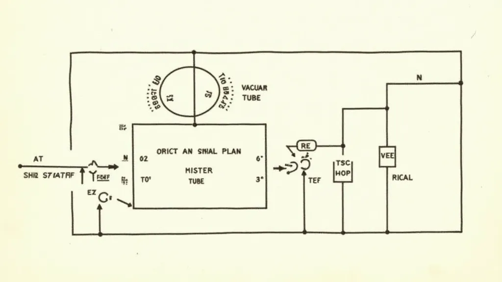
Tracing Circuits: Following the Flow of Signal
Tracing a circuit involves following the path of the radio signal, from the antenna to the speaker.
- Start at the Antenna: Identify the components connected to the antenna input.
- Follow the Signal Path: Carefully trace the connections between components. Note the order in which they are arranged.
- Identify Key Stages: Recognize distinct stages, such as the oscillator, mixer, amplifier, and detector.
- Look for Bypass Capacitors: These capacitors help to filter out unwanted noise and interference.
- Understand Voltage Levels: Pay attention to voltage markings (+ and -) – these indicate the polarity of the signal.
Often, schematics will use different colors or line styles to differentiate between power supply lines, audio signal paths, and RF (Radio Frequency) circuits. These visual cues can make tracing significantly easier.
Dealing with Modifications and Repaired Sections
Vintage radios often have undergone modifications or repairs by previous owners. These alterations might not be documented on the original schematic.
- Look for Handwritten Notes: Carefully examine the schematic for any handwritten notes or markings.
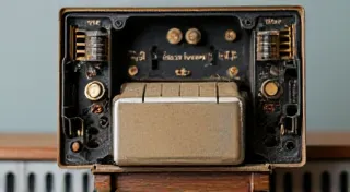
- Compare the Schematic to the Physical Radio: Visual inspection of the radio's wiring and components is essential. Discrepancies between the schematic and the physical radio indicate modifications or repairs.
- Use a Multimeter: A multimeter can help you identify deviations from the schematic's expected values.
Document any discrepancies you find and treat them with caution. Improper modifications can cause malfunction or even damage to the radio.
Resources for Learning More
Mastering radio schematics takes time and practice. Here are some resources to help you along the way:
- Antique Radio Forums: Online forums dedicated to antique radio repair are invaluable for asking questions and sharing knowledge.
- Radio Repair Manuals: Many manufacturers published detailed repair manuals for their radios. These manuals often include schematics and troubleshooting guides.
- Online Schematic Databases: Several websites offer searchable databases of radio schematics.
With patience and dedication, you can unlock the secrets of these magnificent vintage radios, keeping their history and music alive for generations to come.